Gear reducers are used in all industries, they reduce speed and increase torque. They are found between prime movers (e.g. electric motor, engines, etc.) and the driven equipment (e.g. pump, conveyors, etc.).
The project brief was to design a power take-off (PTO) gear reduction unit to drive a hydraulic pump which must deliver 25 litres/min of oil at 150-bar pressure, from a 45 kW industrial diesel generator running at a steady crankshaft speed of 2800 revs/min. Other constraints were also taken into consideration such as infinite life for the shaft, 20,000 hours of life for gears and 12,000 hours for other parts. As well as, consideration of compactness, low weight, low cost, ease of manufacture and assembly for a batch production of 10,000 units per year.Hover on image below for 3.14s to expand.
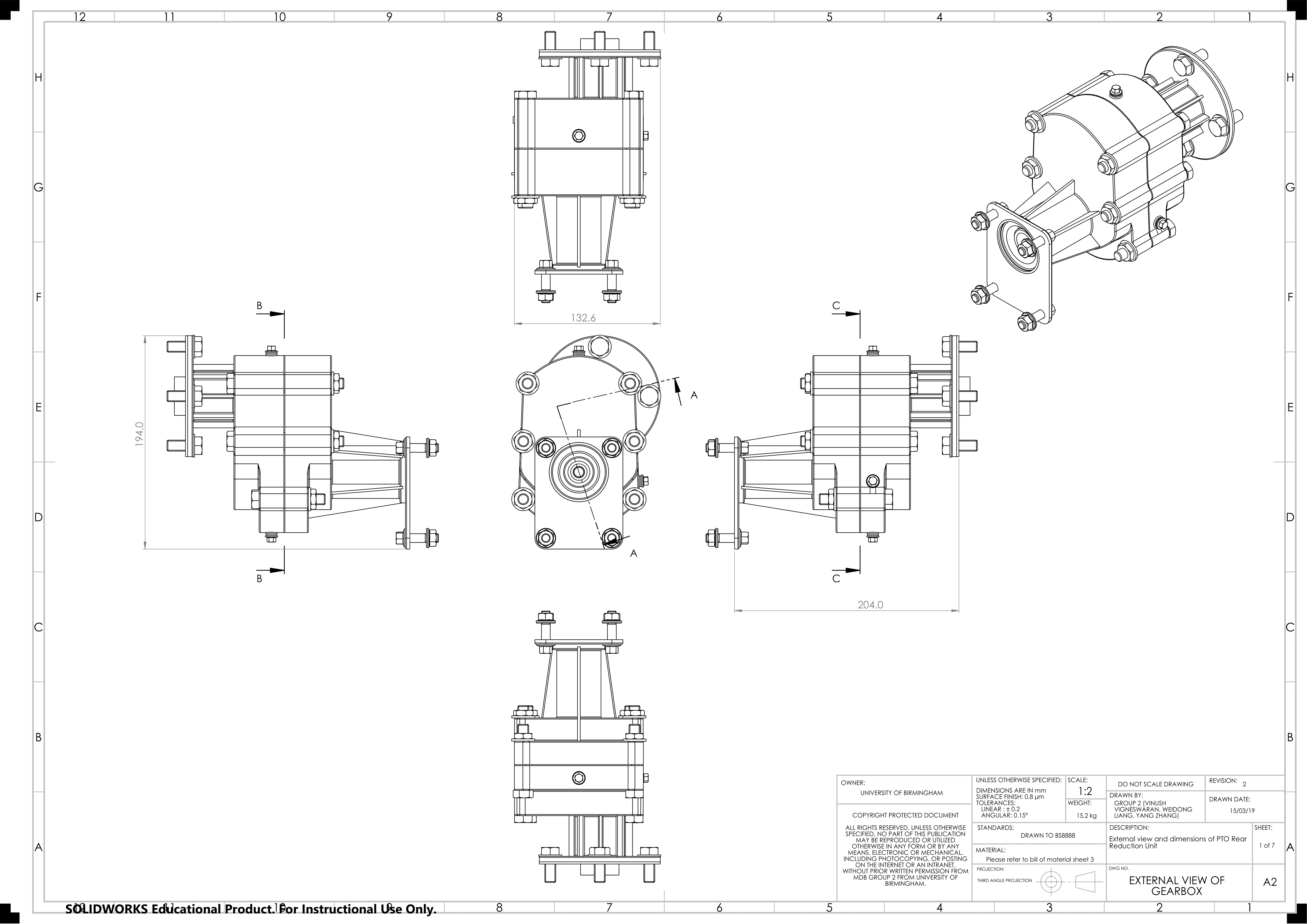
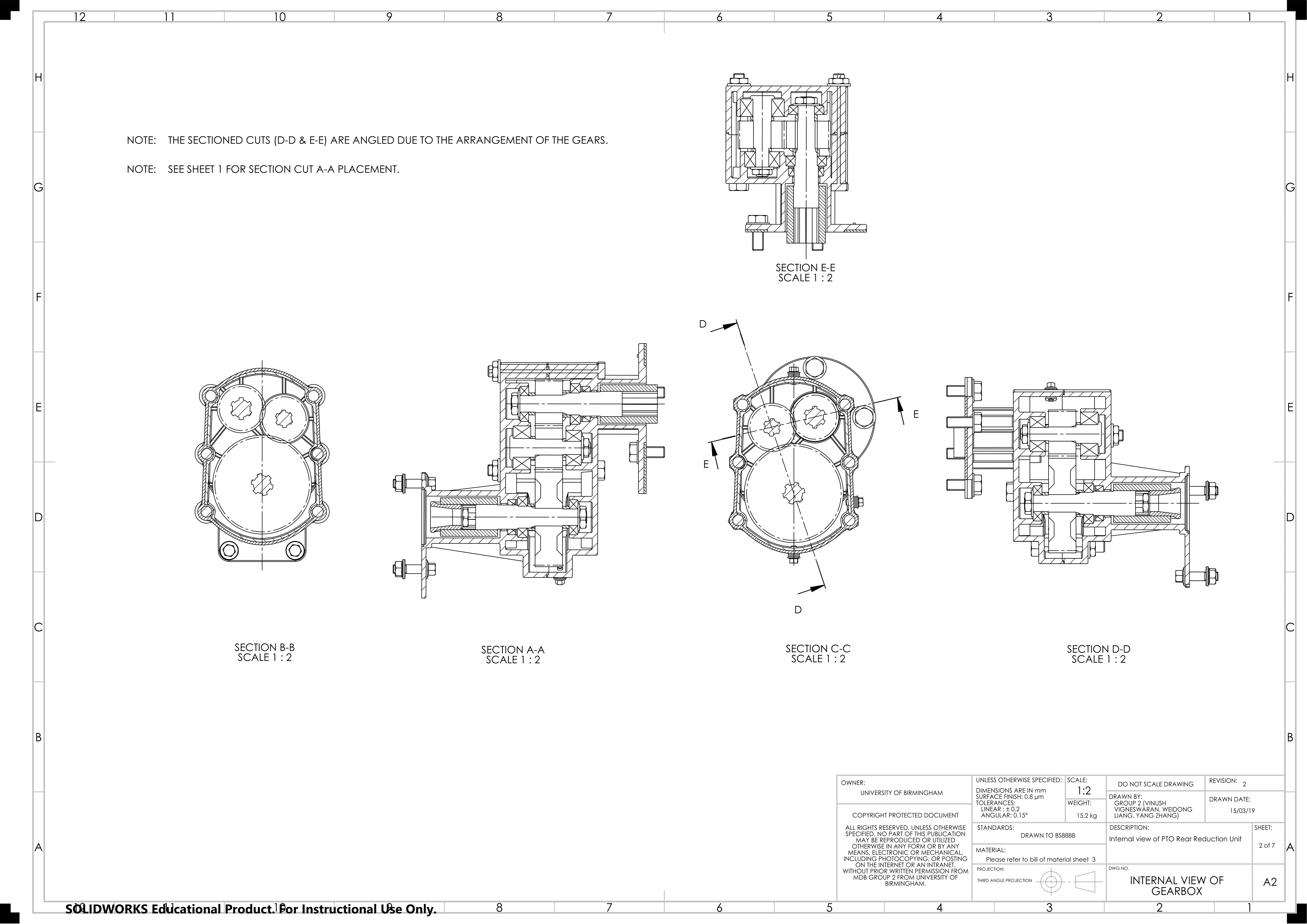
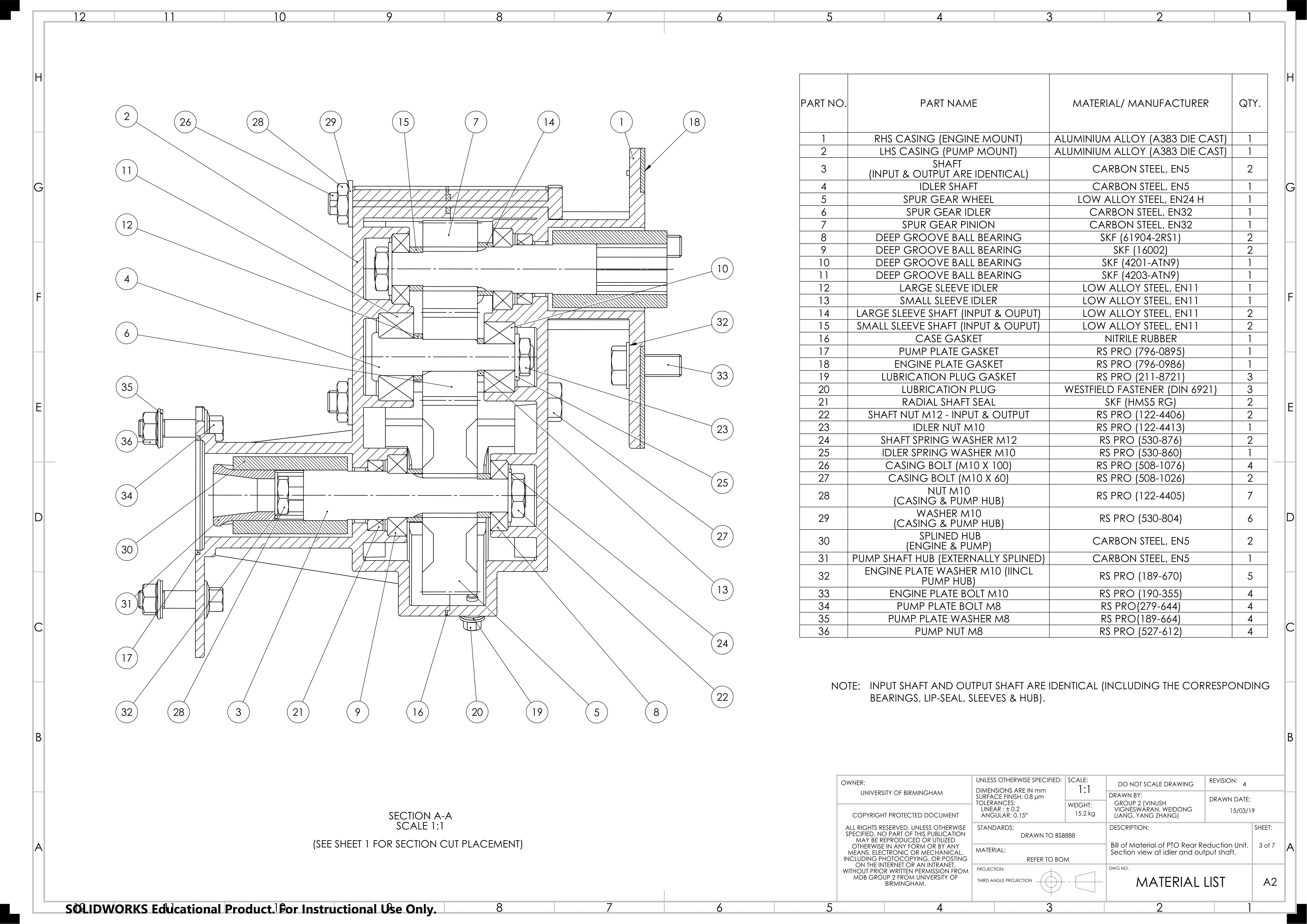
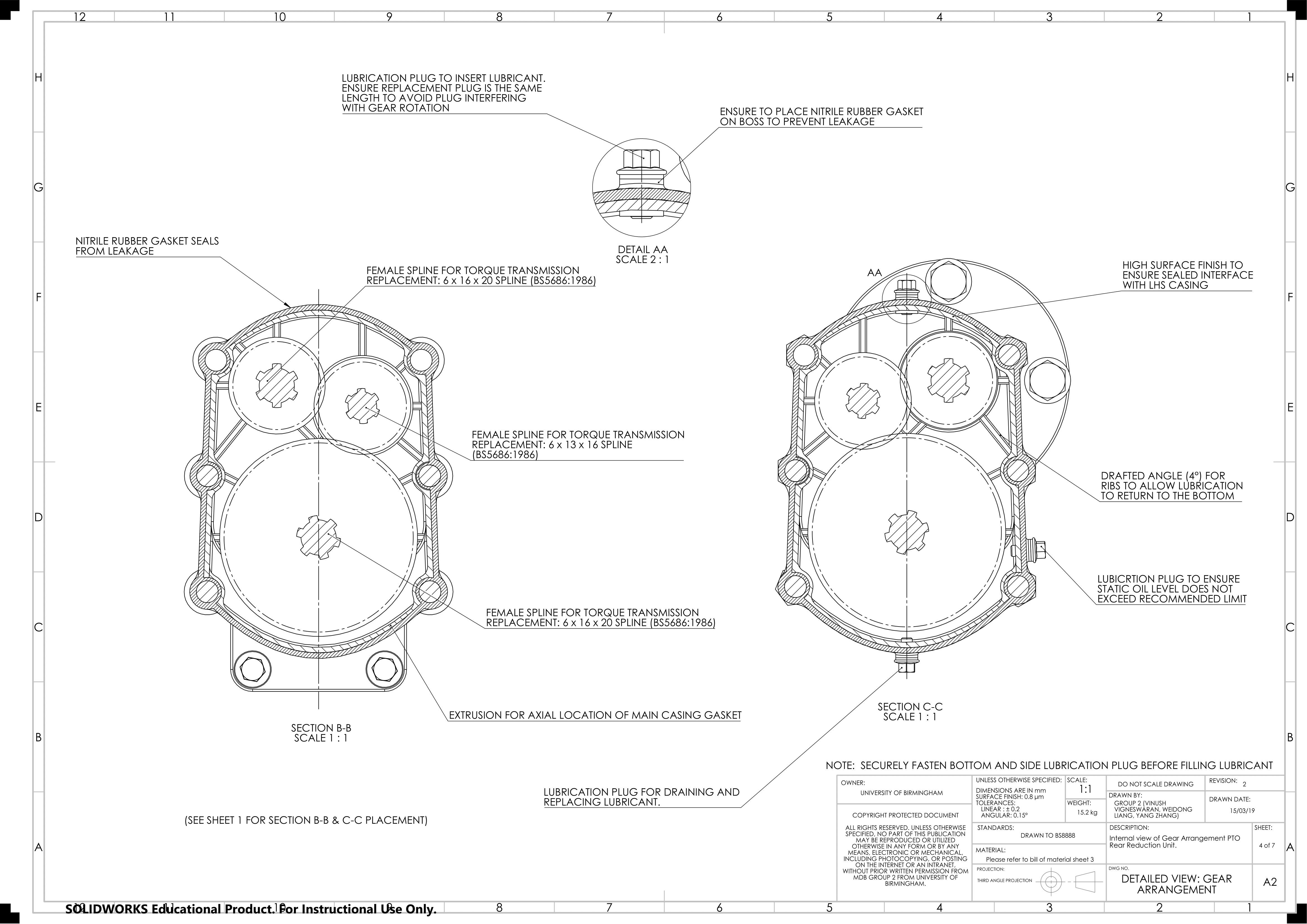
Spur gears were used for this product due to the ease of manufacturing, assembly and high-power transmission efficiency. They are also compact and easy to install/replace. The most common disadvantage of spur gears, are that they are noisy at higher speeds, this can be reduced by considering secondary processes such as grinding, to provide a “fine” surface finish. The output and input shaft rotate anticlockwise (three gear configuration).
The gears are designed to reduce the speed from the engine to the pump by a factor of 2.15. The pump speed of 136.1 rad/s will provide a flow rate of 25 liters/min of oil at 150 bar pressure.
In the slideshow above you will see the proposed gear design (slides 1-7).
In this project, the task was to design a 2-stroke single cylinder compression ignition engine for an Unmanned Arial Vehicle (UAV). The engine parameters include 17:1 minimum compression ratio, maximum power of 300 W, maximum torque of 0.18 N.m, capable of operating at a speed of 16,000 rpm.
In the slideshow above you will see the proposed engine design (slides 8-15).